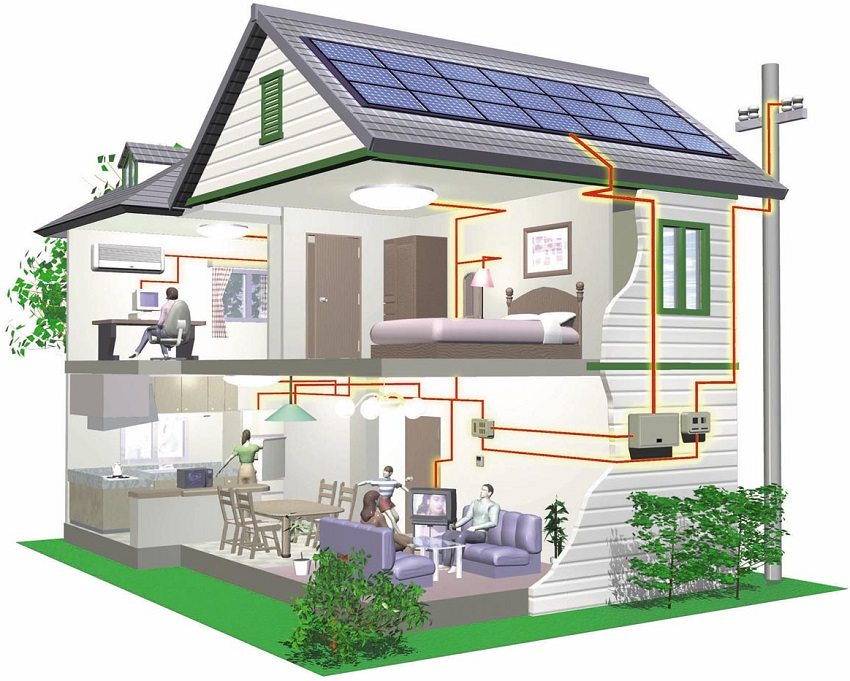
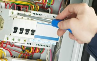
Due to the economy of construction, ease of construction and environmental friendliness, many people prefer wooden houses. A significant disadvantage of such buildings is the increased fire hazard. In this regard, special attention should be paid to the issue of power supply of a wooden house. With strict adherence to the recommendations, do-it-yourself electrical wiring is carried out safely and efficiently in a wooden house. Step-by-step instructions will also come in handy in this matter.
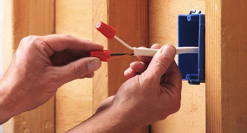
Installation of electrical wiring in a wooden house must be performed taking into account all requirements and rules
Content [Hide]
Do-it-yourself electrical wiring in a wooden house: step by step instructions
The main requirement for the electricity supply of private houses, especially those built of wood, is safety. The installation of the external and internal electrical supply system must be carried out in compliance with all norms and rules. The documents regulating the conduct of electrical wiring are the Electrical Installation Rules (PUE), Building codes and regulations - the section "Electrical devices", GOST and other regulations.
Fulfilling the requirements of norms and rules, it is possible to carry out installation electrical wiring in the house with your own hands. The step-by-step method of performing work includes the following stages:
- determination of the total capacity of electrical equipment and the implementation of the power supply project;
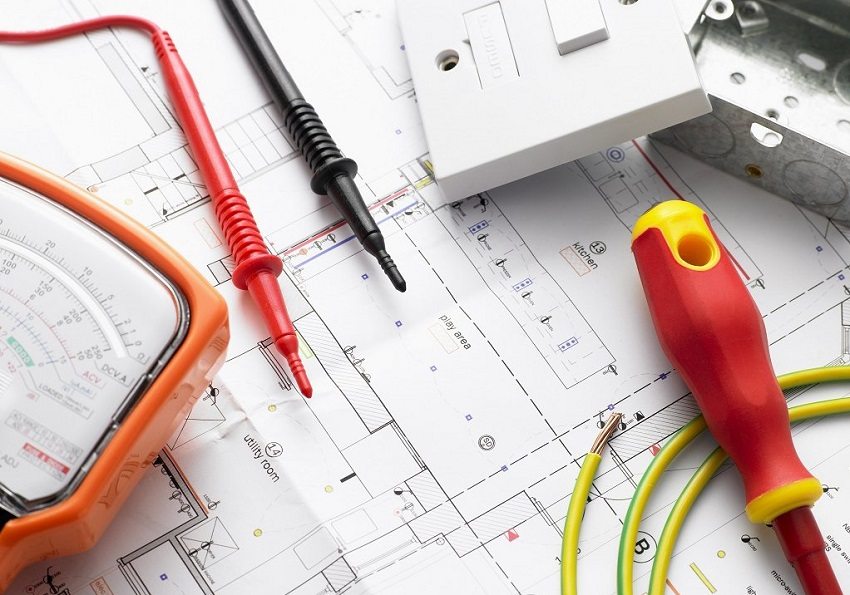
It is better to entrust the development of a power supply project for a wooden house to specialists.
- selection of cables, electrical devices (sockets, switches), electrical appliances;
- implementation of power input into the house, connection of a circuit breaker, connection of a metering device (counter), electrical board;
- internal cable routing;
- installation of switches, sockets and lighting devices;
- earthing system construction, installation RCD (residual current device);
- organization of preventive tests.
Preparation of a home power supply project
To start developing an individual project, it is necessary to obtain technical conditions from the power supply organization (RES). They will become the basis for the work.
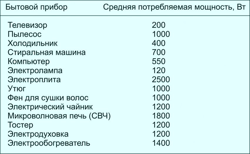
First of all, the total (total) power of all electrical devices is calculated. Next, a do-it-yourself electrical circuit in the house is being developed in stages:
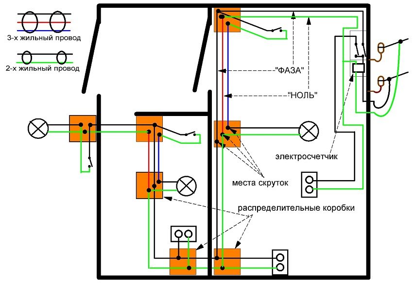
- the technical plan of the entire housing construction is being carried out. In the wiring diagram in a private house, the locations (points) of the location of electrical outlets, switches, lamps, as well as electrical appliances with a separate connection are recorded;
- for each electric point, the type of cable leading to them is selected. If switches with two buttons and sockets with grounding are used, then a three-core cable is connected to them;
- the electrical wiring diagram in a wooden house indicates the installation locations of the junction boxes. It is recommended to use one box for two adjacent rooms;
- the power of each device is reflected on the wiring diagram in a private house. If the device has an electric motor, the value is indicated taking into account the starting power of the electric motor;
- all lighting devices (chandeliers, sconces, etc.) are connected in one group, and more powerful devices (boilers, boilers, electric furnaces, etc.) are combined into another group. For them, it is supposed to bring a cable and connect through a separate machine;
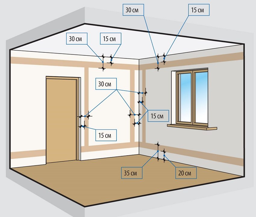
- the diagram shows the distance from the cable passage line to the opening of doors, windows, as well as the distance from the electric points to the floor and ceiling. In the future, this will help to avoid damage to the electrical wiring during repair work.
Useful advice! All turns of the internal wiring cable must be made exclusively at an angle of 90 degrees.
After that, the calculation of the maximum power consumed by all electrical devices when they are turned on simultaneously. Determine the rated load on the input (first in the course of the power supply) automatic machine.
Selection of the appropriate cable and electrical devices
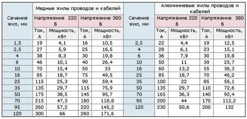
To correctly carry out the wiring in a private house with your own hands, avoiding complex special calculations, you can use the "Table of the ratio of cable cross-section to the corresponding load" from the electrical reference book.
From the table, select a cable cross-section that will correspond to the power of electrical appliances for each individual group. Each device is accompanied by a description or technical data sheet, which indicates the load it consumes. Based on this data, an acceptable cable is selected. In order to determine the cross-section of the input cable, you should add up the power of all available devices.
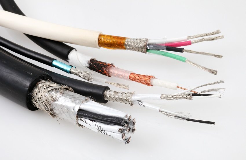
The most popular cable for wiring is NYM copper cable. It has additional insulation, is strong enough and easy to handle. In the case of using an aluminum cable, it must be borne in mind that it is vulnerable to bending and often breaks when cut.
The sockets are supplied with a three-core wire with groundingto ensure the safety of household electrical equipment. Lighting devices, according to the Electrical Installation Rules, also need to be equipped, although many neglect this norm. If in a private house powerful searchlights are used to illuminate the territory of the courtyard and the site, then the organization of grounding is a prerequisite. This rule also applies to those who decided to do the wiring diagram in the country with their own hands.
Sockets and switches are selected based on the calculated value of the current, the type of wiring (hidden or open), the possibility of connecting the unit with socket and switch under one frame.
Selection of the lead-in cable and circuit breaker at the input
Having calculated the rated load of all electrical appliances intended for installation, the cross-section of the input cable is determined. For those cases when the electrical wiring is being updated with the replacement of internal wires and machines with more powerful ones, one should not forget about the cable at the input. It may happen that its cross section is not enough for too high power - this can provoke a fire. Therefore, you must contact the appropriate organization to replace the lead-in cable. This can be done at the stage of installing the meter and sealing it.
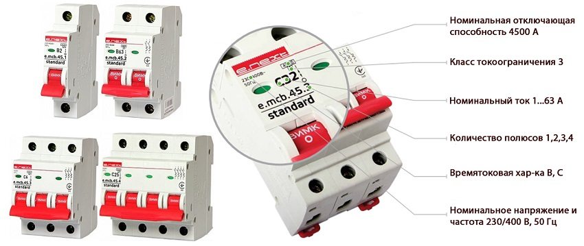
As for the input machine, a three-pole circuit breaker is used with a three-phase power supply. If the power supply is single-phase, which occurs in 90% of cases, a one- or two-pole circuit breaker is used that breaks the phase and neutral.
Useful advice! The input circuit breaker is selected with such a rating so that it does not turn off the power to the house at maximum load, but breaks the circuit to prevent a short circuit.
Rating and type of machine for single-phase power supply
The circuit breaker is selected based on the following:
- determine the sum of the power of all electrical equipment and calculate the value of the maximum current using the formula: Ihom = P / U x cosϕ. The value of cosϕ is taken as 0.8. A correction factor of 1.1 is applied to the obtained rated current Ihom. As a result, the maximum current is obtained at which the machine is triggered. A 25 A circuit breaker is usually sufficient for home input;
- to determine the type of machine, you should know the minimum value of the short-circuit current. The formula for determining the current in a single-phase network (220 V) is as follows: Isc = 3260 x S / L, where S is the cable section, (mm²); L - cable length, (m). This formula determines the current for the longest section with the smallest wire section;
- the ratio of the short-circuit current to the rated current determines the characteristics of the circuit breaker. The recommended machine for installation in the house is a circuit breaker with a characteristic C. This machine works perfectly in networks with mixed loads.
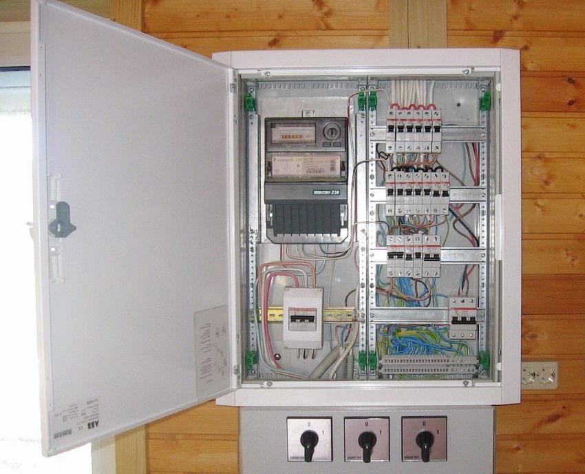
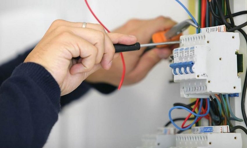
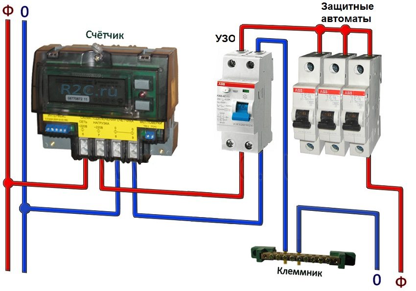
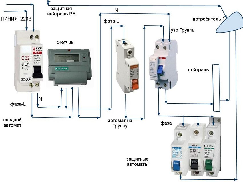
According to the wiring diagram in a private house, they install an introductory machine after the metering device with their own hands. Automatic switches for devices combined into one group, a metering device, an introductory circuit breaker and an RCD are mounted in an electrical panel on a special metal profile (din rail). Next, the wiring is carried out according to the wiring installation scheme in a private house.
Do-it-yourself electrical wiring in a wooden house: installation
Installation of electrical wiring begins as soon as all the necessary devices are purchased: cable, sockets, switches, machines, lighting devices.
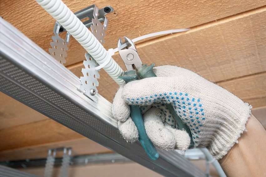
According to the existing scheme, junction boxes are mounted, fixing points of sockets, switches and lighting devices are fixed. If all the walls in the room will be sewn up with finishing material, the cable is laid in a metal sleeve.
Do-it-yourself installation of a switchboard
The electrical panel housing is fixed in the place specified by the circuit. After that, do the following:
- a metering device is mounted in the dashboard housing;
- an introductory machine is installed on a special metal profile (din rail). Phase and neutral are supplied to the two-pole circuit breaker;
- the output clamps (terminals) of the meter are connected to the input of the input circuit breaker;
- the wire is brought into the house and connected to the input terminals of the meter (meter);
- voltage relays, automatic machines for different power groups (sockets, lighting devices), RCDs are mounted on a din-rail;
- clamps of electrical appliances are connected with a single-core cable.
Cable entry into the room
Power cable entry into wooden house must be carried out in accordance with PES and SNiP.
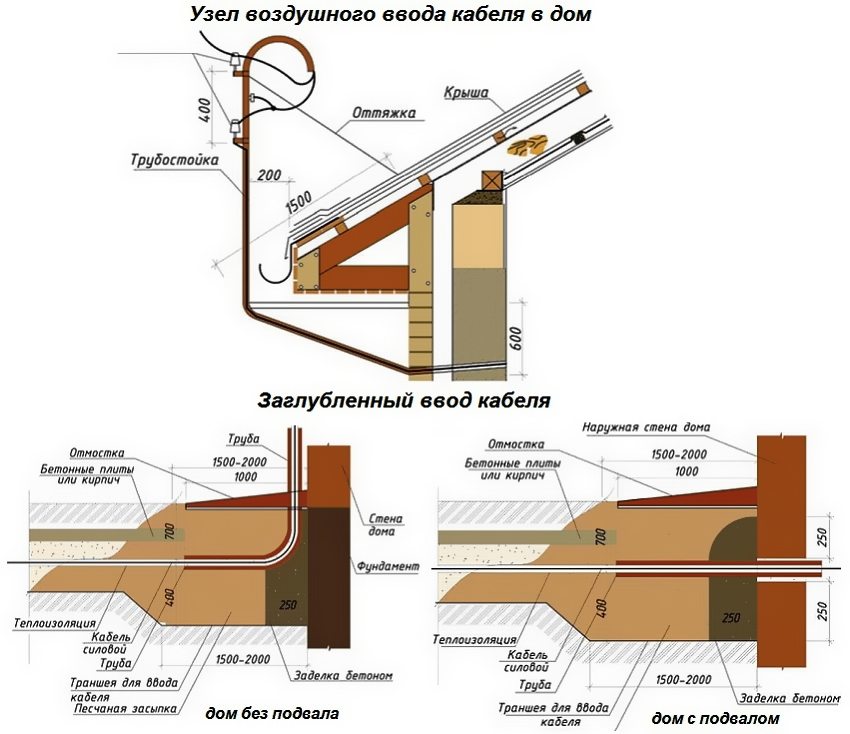
The lead-in cable can be brought into the room by air or underground. It should be noted that the air method is less costly, but not entirely reliable. In such cases, self-supporting insulated wires (SIP) are used. With the air method of inlet, a prerequisite is the installation of a fireproof sleeve in the wall through which the inlet will pass.
An underground wire is laid underground in a metal pipe that protects it from all kinds of influences. Such cable laying must be coordinated with the power distribution company.
Wiring device in a wooden house: rules for internal cable laying
If the project provides for open wiring, several ways of its installation should be noted:
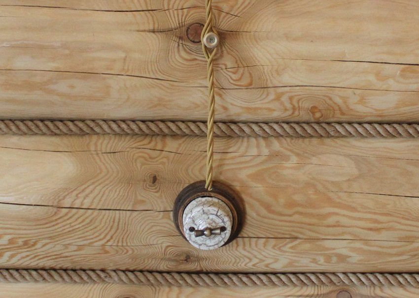
- ceramic rollers for open wiring - this method is convenient for laying the wire along a wall of logs. Will be appropriate in a retro interior;
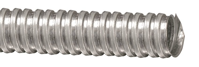
- metal pipes - this method reliably protects housing construction from fire. Pipes should be filled with wire no more than 40%. It is recommended to use copper wire that bends easily;
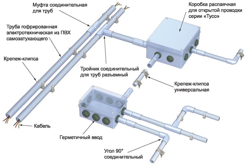
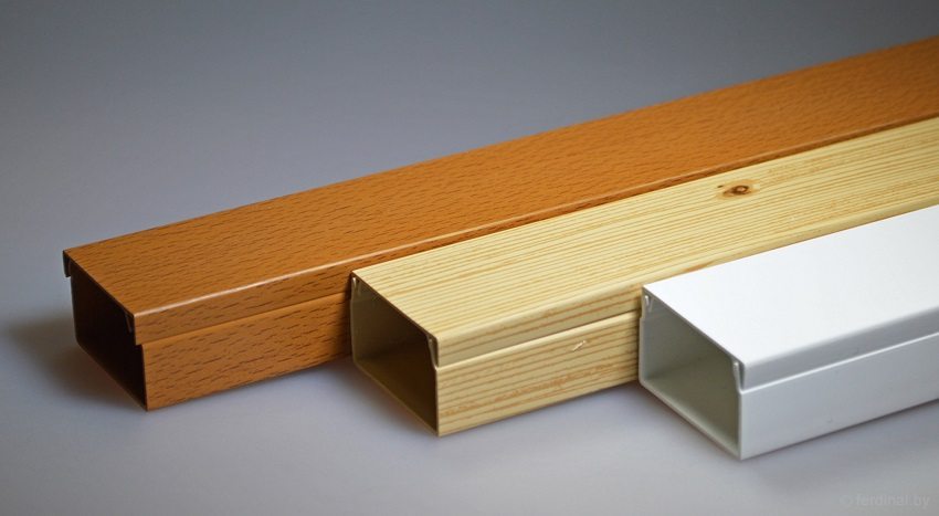
- plastic cable channels - the channels are attached to the wall, you can choose plastic channels of various colors to match the wall decoration;
- plinth with a special channel (chute) - with this method in channels skirting boards clamps are installed to secure the wire;
- fastening with staples - plastic staples are selected according to the size of the wire section. This method is most often used for wiring in utility rooms due to its unattractive appearance.
Useful advice! All passages of the electric wire from room to room through the wall must be equipped with metal fireproof sleeves through which the cable is pulled.
In some cases, the cable is laid under a plank floor using metal pipes.
Wall mounting of a wire in a cable duct
It is possible with the help of cable channels to mount electrical wiring in a wooden house with your own hands. Step-by-step instructions for laying wires in a cable channel:
- mark the line of the wire passage, according to the existing diagram;
- the cross-section of the cable channel depends on the number of wires placed in it;
- remove the cover of the box and fix it with self-tapping screws to the wall or ceiling. Self-tapping screws are placed at intervals of half a meter. Places of turns are additionally strengthened with self-tapping screws;
- junction boxes are mounted in established places;
- the necessary wires are laid in the cable channels and snapped with a cover. In places where sockets and switches are connected, a supply of wires is left for their connection;
- connect all wires in junction boxes, connect to the clamps of machines, switches and sockets.
The installation steps can be seen in various photos of electrical wiring in a wooden house.
Wire connection procedure
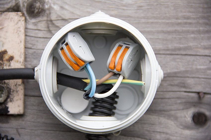
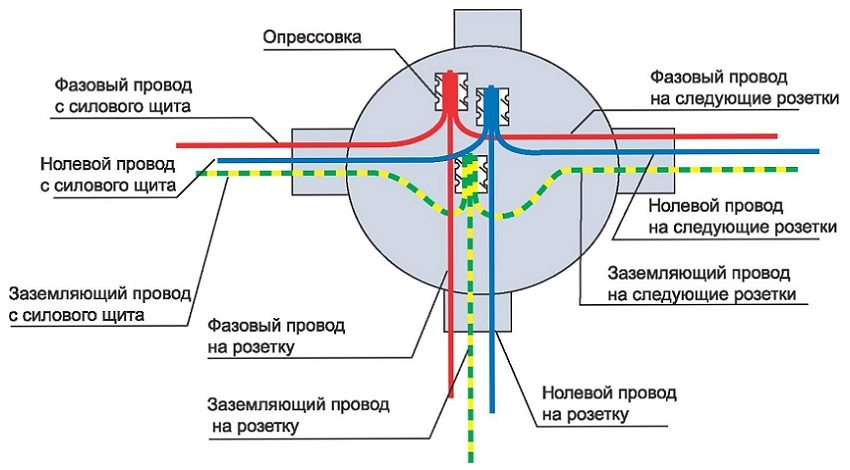
The rules stipulate wire connection inside the junction boxes. The boxes are installed in places where there will be branches from the main cable. Wires are connected by the following methods:
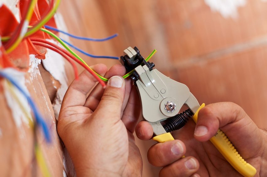
- the connection can be made using self-clamping terminals (Wago).With this method, it is enough to remove 10 mm of insulation from the wire. The terminals are selected according to the size of the wire cross-section together with the insulating cover;
- it is possible to connect the wires with insulating twist caps. With this method, the insulation is removed from the wire so that the length of the bare section does not exceed the length of the cap. It has a conical spring inside. When the cap is screwed onto the twist, the spring securely grips the wire, and the plastic sheath provides insulation;
- twisting connection involves cleaning the wires from the insulating coating by 4 cm and twisting tightly. All twists are recommended to be soldered and wrapped with insulating tape.
Useful advice! The number of wire connections in the network affects the system's ability to carry loads: the more connections, the lower the load capacity.
When connecting wires, consider the color of the insulation. Red, brown insulation - wires with a phase, blue, white - neutral (zero), yellow, greenish - grounding wire.
Grounding device and RCD installation
Modern home furnishing with household appliances is not complete without such electrical appliances as boiler, washing machine, refrigerator and many others. The presence of electrical equipment with a metal case requires a mandatory grounding device.
The order of the grounding device is as follows:
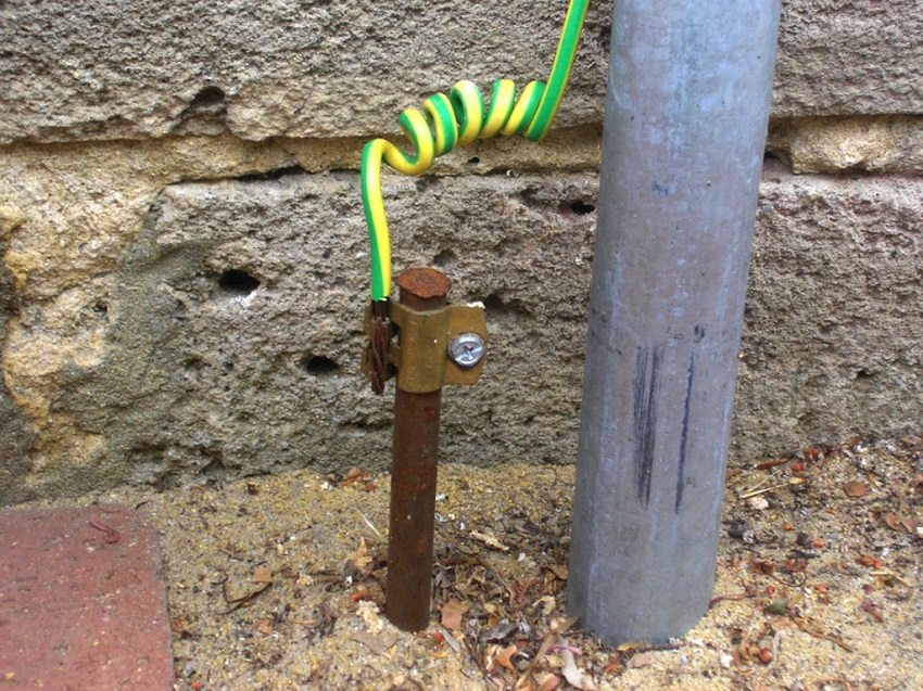
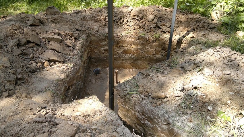
- three reinforcement rods 3 m long and 3 cm in diameter are being prepared. A trench is dug in the form of an equilateral triangle with a side length of 1 m. The depth of the trench is 30 cm. The reinforcement is placed in the ground at the corners of the resulting triangle;
- reinforcement rods are connected to each other with a metal corner by welding;
- a loop (eyelet) is welded to one of the corners and a 1 cm thick steel rod is attached using a screw connection or by welding.
- the rod is laid in the trench in such a way as to connect it to the grounding conductor in the electrical panel. The grounding conductors of the cables have yellow-green insulation.
To protect a person from electric current when it leaks onto the body of electrical equipment, a residual current device (RCD) is used. This device is mounted in a panel after the meter. Based on the value of the rated current in the network, the parameters of the RCD are selected, which reacts to the slightest leakage of current. The presence of such a device is especially important for rooms with high humidity.
Related article:
Do-it-yourself grounding in the country. Electrode installation diagram. Layout of grounding elements and strapping. Grounding schemes in private houses, materials for the circuit, installation.
The rated value of the current for the RCD is taken higher than the current of the machine in this circuit. The leakage current is based on the type of room. For a bathroom, the best choice would be an RCD with a leakage current of 10 mA, for other rooms, 30 mA.
Testing electrical wiring
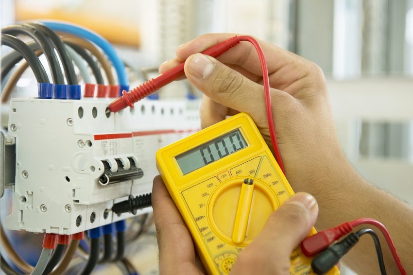
Electrical wiring tests are carried out using precision electrical measuring devices by specialists from certified electrical laboratories. The set of tests includes:
- visual inspection;
- measurement of the resistance of the cable insulation;
- preventive measurement of grounding resistance;
- checking of circuit breakers;
- phase-zero circuit check;
- testing of protective devices;
- checking the circuit between the devices and the earthing switch.
Upon completion of the work, a test report is issued.Timely tests of devices and electrical wiring guarantee the prevention of breakdowns and accidents that can damage equipment, disable all wiring and harm human health.
